- #Delco remy 3 wire alternator wiring diagram how to#
- #Delco remy 3 wire alternator wiring diagram install#
- #Delco remy 3 wire alternator wiring diagram professional#
- #Delco remy 3 wire alternator wiring diagram series#
- #Delco remy 3 wire alternator wiring diagram download#
It's simpler to establish circuits and connect the alternator appropriately when you have a clear picture of each component's existing schemes and location. Wiring diagrams show how the connections and physical architecture are connected. This type of schematic is advised for enhancing your car unless you are ready to strictly control your budget of electrical systems when travelling at low speeds.
#Delco remy 3 wire alternator wiring diagram download#
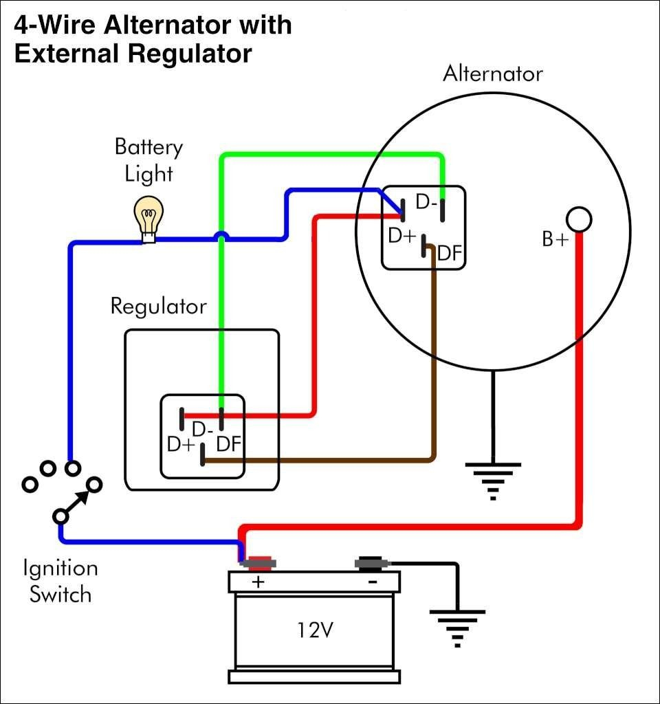
Just because two more wires are incorporated into the overall electrical system, this alternator wiring schematic is far less invasive. Download our Delco Remy Resource Library from the App Store for easy access to. The main charging wire, a wire that can switch between the regulators, and the electromagnet wire are the three wires in the alternator wiring schematic that uses 3 wires. What's important to remember about this wiring system is that it may help you increase your vehicle's electrical properties to fit your demands. Due to this, all parts receive regulated voltage when a 3-wire alternator wiring schematic is used. These systems can work to produce power in the circuit, unlike alternators which are single wires. Different purpose alternators are available that have built-in systems for voltage and power monitoring. The energy detection cable monitors voltage and transmits it to the converter, while the energy wire links the alternator and the engine. The ignition input wire is linked to the engine. There are three key wires in the loop: a positive wire for the battery, a sensing wire for voltage, and an igniting wire.
#Delco remy 3 wire alternator wiring diagram install#
With the proper knowledge and understanding, you can easily install and maintain your Delco alternator wiring system.The connections between the different circuit parts are shown in an alternating schematic based on 3 wires. Installing and troubleshooting wiring diagrams for Delco alternators is not a difficult process, but it is important to know the basics of reading and interpreting them.

#Delco remy 3 wire alternator wiring diagram series#
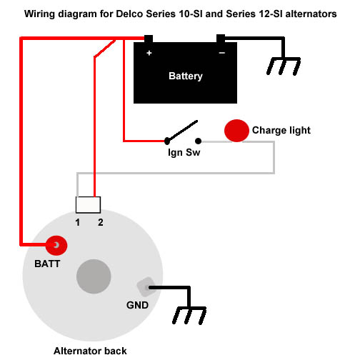
This first section will cover wiring information for the SI series only, we will go over the CS and AD series wiring later. The large 'BATT' terminal which gets connected to your battery.replacing a 20dn, 30dn, 41 dn, and d.c. Since the introduction of the 10Si, GM's Delco-Remy line has offered the 12Si, 15Si, 17Si, 27Si then the CS and AD series alternators for cars and light trucks.

The 10SI has three terminals (including those with a 1 wire regulator). (SI and SI Series are identical except stator is a delta.).
#Delco remy 3 wire alternator wiring diagram how to#
Also, make sure to double-check all of the connections before powering up the system. How To Wire A Gm External Regulated 10dn Alternator. Figure 5-Typical SI wiring diagram showing internal circuits.
#Delco remy 3 wire alternator wiring diagram professional#
Always follow the instructions that come with the diagram and if you're unsure, consult a professional electrician. Once you've read the diagram, you can now begin to install the wiring. For instance, if you see a red wire, it usually means that it's the primary power source for the system. Each wire is represented by a different color, which can help make it easier to trace the wires and interpret them correctly. One of the most important aspects of reading a wiring diagram for Delco alternators is the color coding. Once you understand the components and how they interact with one another, you can then begin to interpret the diagram. Most diagrams will have a legend at the bottom that will explain each component and what it does within the system. Once you've chosen the type of diagram you want to use, it's time to start reading it. Both types of diagrams are fairly easy to read, as long as you take the time to understand the components and connections. Pictorial diagrams show the various parts of the alternator in a schematic layout, while schematic diagrams show the electrical connections between the components. The most common formats are the pictorial and schematic diagrams. When it comes to reading wiring diagrams for Delco alternators, there are several different formats available.

This is why having the correct wiring diagrams is so important. The connections between the different circuit parts are shown in an alternating schematic based on 3 wires. If there are any miswirings, the system could malfunction or even cause serious damage. Properly wiring an alternator is critical to ensure that the system works properly. Before we begin, it's important to understand why wiring diagrams are so important. In this article, we'll discuss the basics of reading and using wiring diagrams for Delco alternators, as well as provide some helpful tips to get you started. Installing and troubleshooting these diagrams can be a tricky process, but having the right knowledge can make it much easier. If you're looking for an easy way to install and repair wiring diagrams for Delco alternators, you're not alone.


 0 kommentar(er)
